Restoration of a dumpster Tektronix 2465B oscilloscope
A casual date with the dumpster⌗
By the end of June 2023, I came across an interesting finding in the dumpster I usually look up to. A huge blue beast was laying there, a Tektronix analog oscilloscope. I was not expecting to find a scope in that dumpster as I usually only find some computer peripherals and components when I’m lucky enough. However, this old analog scope was there, in pretty good shape, with its blue probe pocket on the top, the original Tektronix handle, and its front cover.
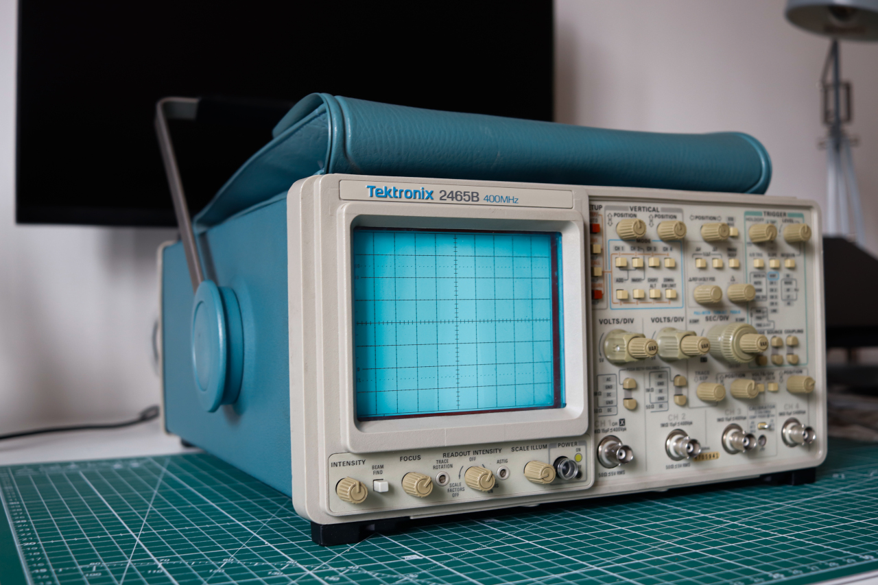
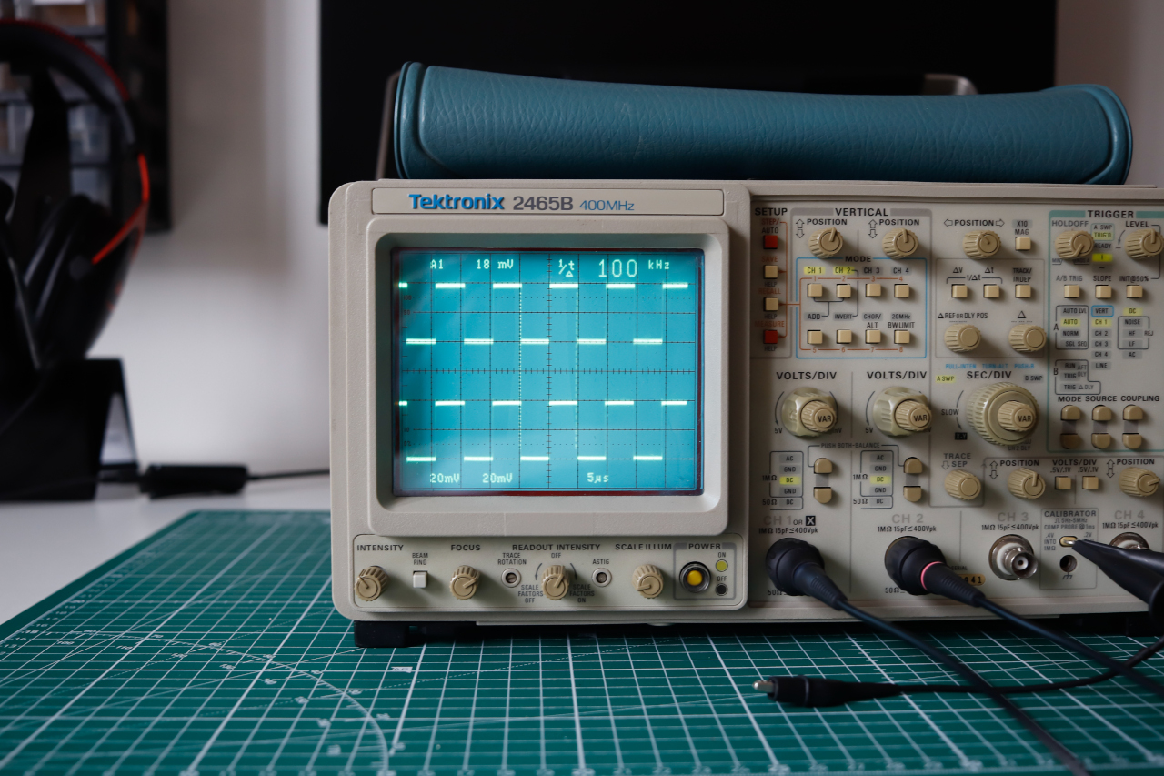
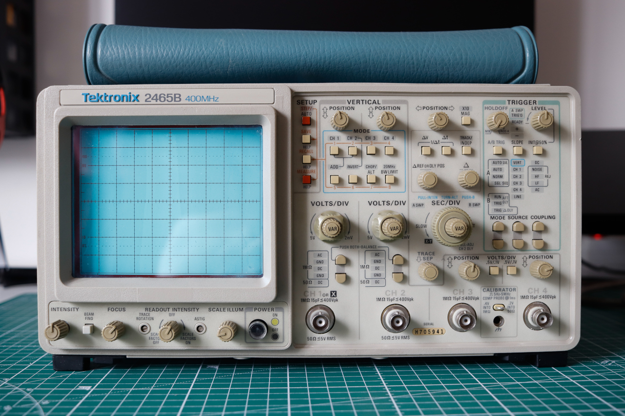
Once I have removed the front cover, I discover the unit’s front panel, unveiling a Tektronix 2465B 400MHz unit. A CRT analog oscilloscope from the 90'. I was hooked. The unit is gorgeous, take a look by yourself!
With its 400MHz bandwidth, it outperforms my regular digital scope Rigol DS1054Z which has a 50MHz bandwidth. I could use it for specific designs where high-frequency signals are used. For example, I could evaluate the quality of digital – square – signals where my digital scope would have filtered near fundamental harmonics frequencies shamelessly. I had to take it home to test it.
Let’s start it up!⌗
On the first start-up, the scope started blinking on many LEDs of the front panel, making relay clicking noises, then got stuck with a green LED light on the ADD mode with nothing displayed on CRT. Wah wah wah wahhhhh…
Maybe it was just a bad start. I mean, modern devices might boot and get lost on track daily. This time, after putting the scope OFF and back ON afterward, it boots! But yikes… readout is inconsistent, might appear, and then disappear right away. Measured signals are noisy as hell, even with the GND coupling, the signal seems noisy and shakes around the zero reference. I was skeptical of the scope ability. After a second reboot, for the sake of certainty, it got stuck again into the ADD mode.
Invisible failing test⌗
After an intense web search, I found many threads dedicated to the scope, such as the EEVBlog teardown thread. Before digging into a deeper troubleshooting process when people had display problems with fading out intensities, the first step was to check out the grid bias parameter of the CRT.
“The adustment of grid bias controls the intensity or brightness of the pattern on the face of the tube, just as the grid bias controls the plate current of an amplifier tube, and at cut-off the pattern is completely extinguished”
- Design of cathode-ray tube circuits (as read on 24th July 2023)
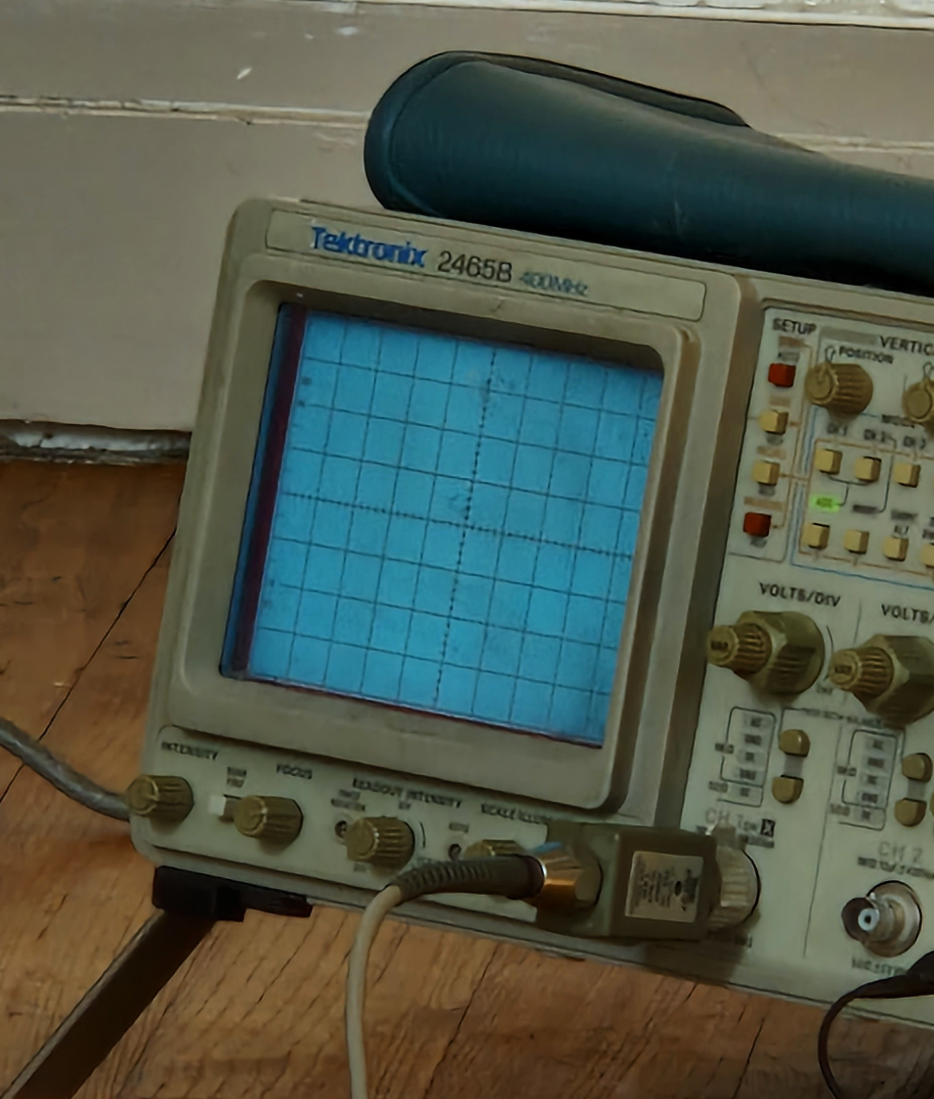
I first had to teardown the scope by unscrewing and dragging the scope’s blue case off to access the CRT grid bias potentiometer. While powered on, I tweak the potentiometer in one direction and observe the changes on the CRT. As the scope had booted into a clear display and the ADD LED was on, I now perceived a written message on the screen.
TEST FAILURE 05-40
Yup, something was wrong. By reading the scope manual, in the Maintenance section, page 234, we can read that the test concerns the main board, as shown below.
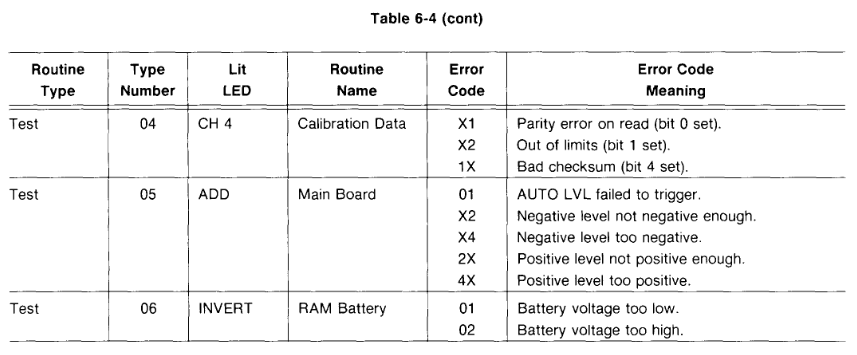
We recognize the behavior of the front panel with the ADD LED being lit as described in the table. The error code 40, which sometimes turns to 44 on different boots, corresponds to Positive level too positive, whatever it means. On page 237, two paragraphs summarize the test case perimeter, as follows:
As the test checks multiple features, I choose to perform a visual check of PCBs in the scope.
Leaky capacitors, again⌗
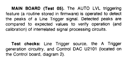
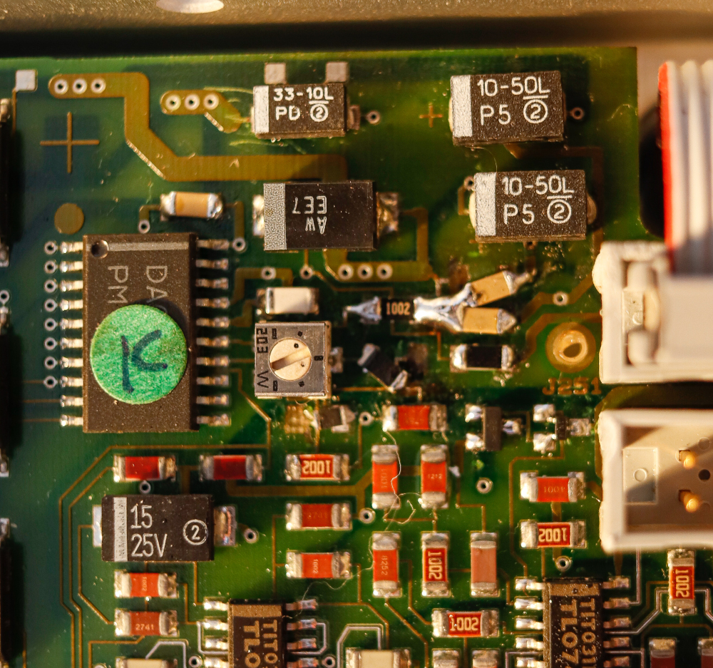
As I looked at PCBs inside the scope, I encountered a series of leaky capacitors on the A5 board. The A5 board referred to the Control board, as mentioned in the documentation. Two areas on the board got leaky electrolytic caps. Here is a photo of the first area identified.
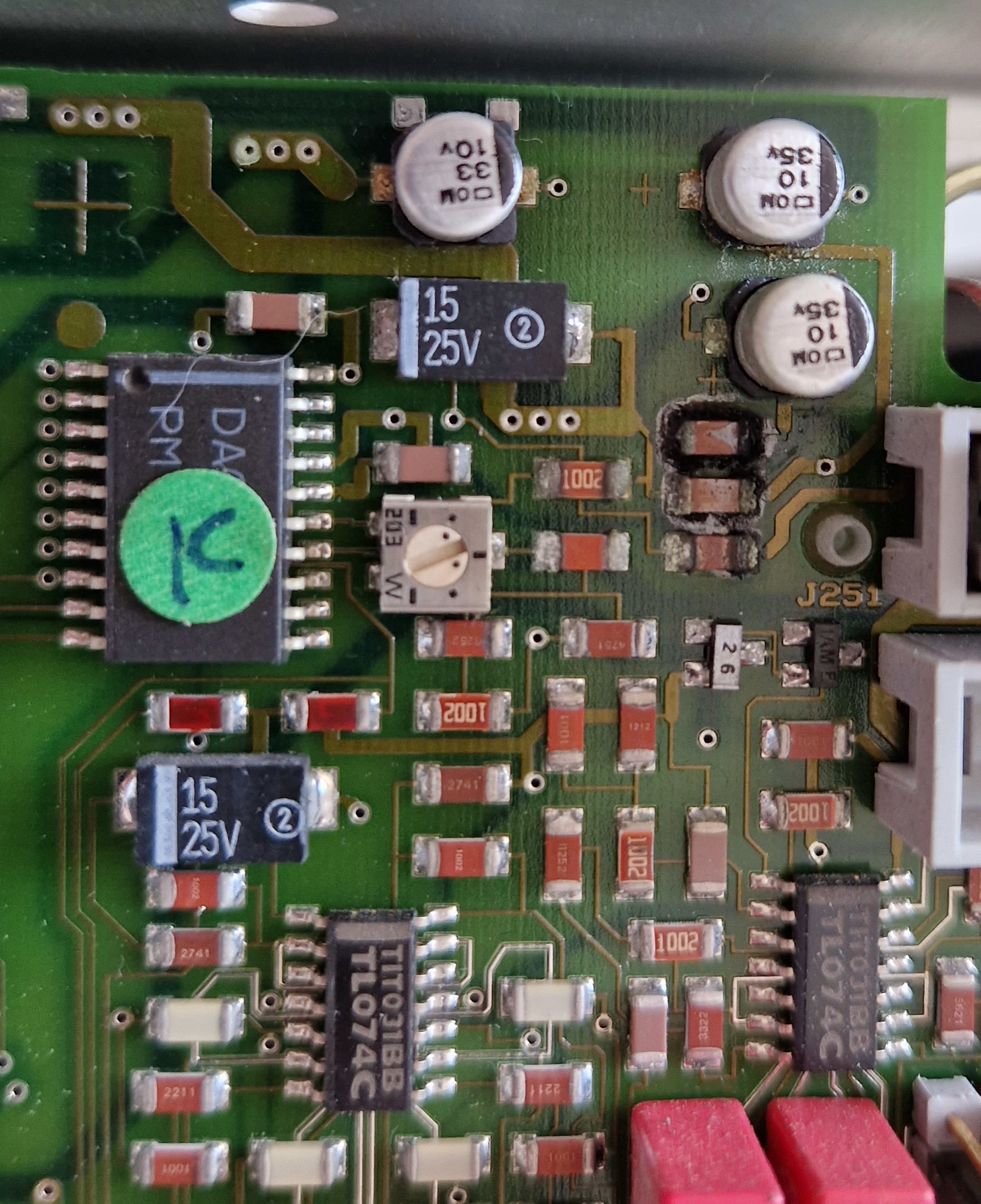
As we can see, the leakage seemed to oxide on several SMD components. The IC with the green sticker is the DAC mentioned in the test check. It might explain why the test is failing, as the leaky capacitors might have derived the electrical characteristics of neighbor components, or even broke them. The same goes for the second area, as pictured below.
The first area are can be found in C1, the second in K1, as visible on the board layout below:
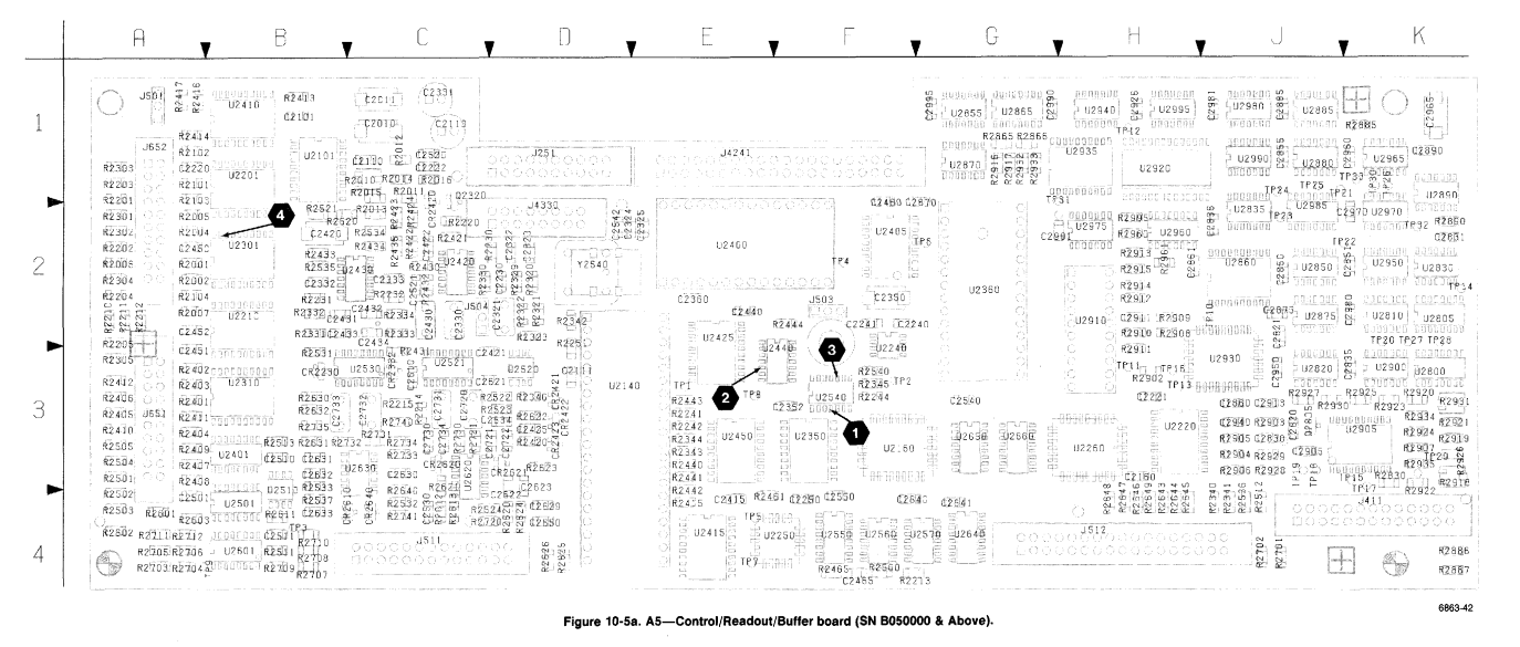
Using this layout, I was able to find component references on board, which will be handy to compose the bill of materials for the replacement.
A known problem⌗
A Wiki page also exists for the scope, on TekWiki. The latter exhibits many external links, including the EEVblog thread and others. One of them is called 2465B SMD capacitor leak repair, which tells the exact problem and how to repair it. This leakage is known as a plague for this scope series.
The document is really good, but do not fit my exact problem: his areas of leakage are larger, then I compose my replacement list with an adequate bill of material.
After identifying the leaky caps and considering dead neighbors, I used page 305 which is the bill of materials of the original board. I have searched for equivalence of all identified components on RS to compose my bill of material for the replacement. Here is the BOM in CSV file. I had sometimes to replace 1206 packages with 0804 ones due to lack of choice. I replaced the aluminum electrolytic capacitors with tantalum ones. This choice is debatable, as tantalum could burn, or produce a micro-explosion, not sure if it is way better than an electrolyte leakage. If you got to do this replacement too, think about getting a polymer one. The electrolytic capacitors that I found had a 2917 package, unsure of what was the original package size for the leaked capacitors, I choose this one as a trial.
Lab upgrade for the occasion⌗
To perform this operation, I have upgraded my setup with a hot-air and soldering station: a Yihua 858D and 937D. I always had stationless soldering iron in the past but I found it was limiting in terms of possible operation and highly frustrating. The hot-air gun will ease the desoldering part of SMD components, especially for integrated circuits.
Let’s repair it!⌗
I performed the replacement in one afternoon. After removing components with the hot-air gun and a pair of twizzle, I tidied solder pads with solder wick.
During the process, I realize that many solder pads got away with electrolyte-affected components, especially in the first area, as shown below. The red-rounded area shows 2 missing solder pads for a ceramic capacitor that was highly damaged by the electrolyte leakage.
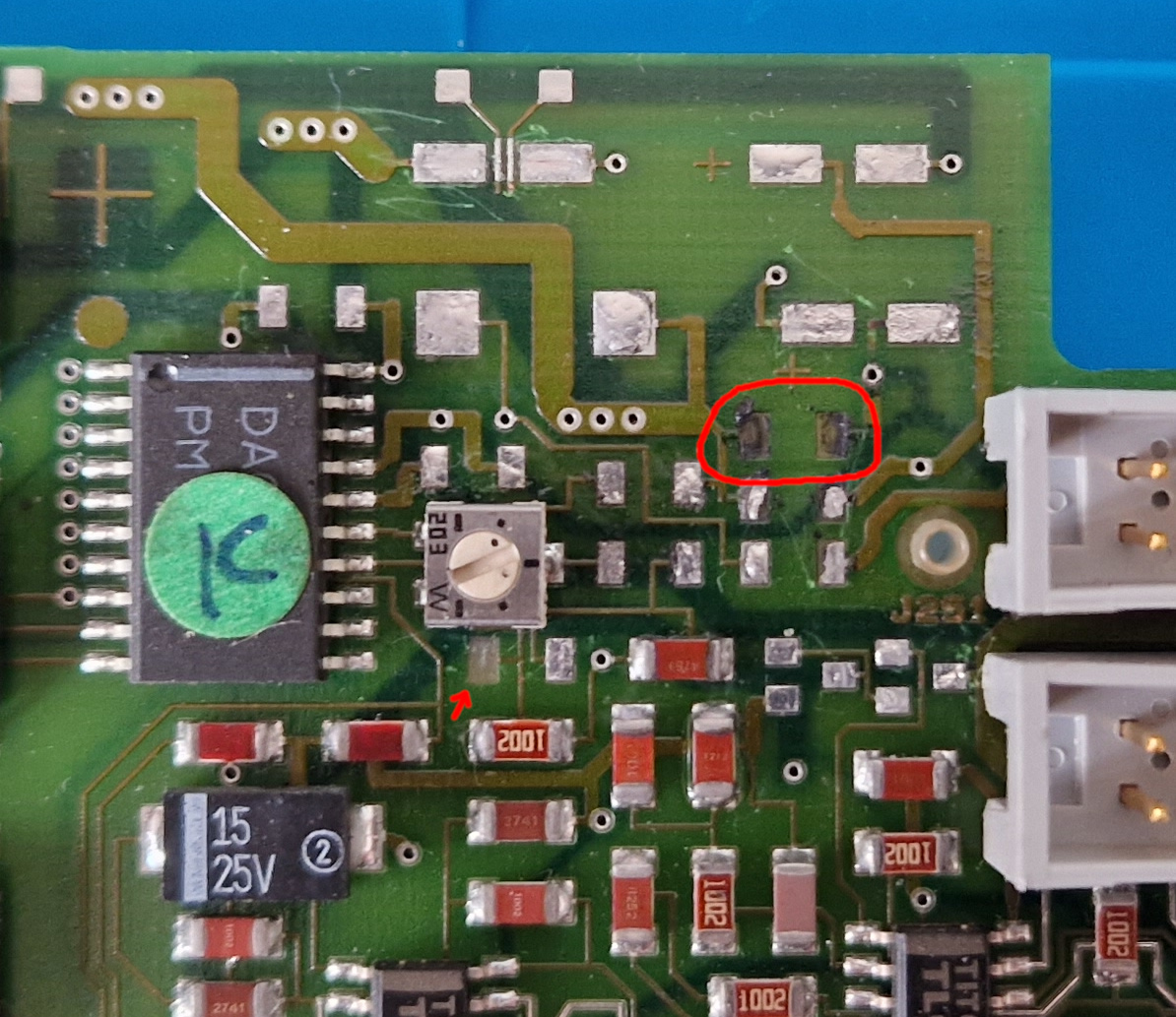
The little red arrow shows my own mistake while removing a resistance that was not even to be replaced, ouch! I had to buy another part in 0804 package, slightly littlier than the original 1206, so I could resolder it by scratching the trace that pass between the two pads of the resistance.
After cleaning the areas, it was time to solder the replacement parts. I started with parts that have fresh and clean pads.
First surprise: damn, the transistor that I chose is a package SOT-523 instead of SOT-23. I had no choice at the time, the same reference was only available in this package, so I thought that it was the same. This was more challenging but still, the SOT-523 packages did fit in the SOT-23 solder pads.
Another surprise: some solder pads seemed not connected to their traces, as the continuity tester was failing while I was trying to solder passive components. I identified a micro-rupture not visible between them, hence I scratched the trace to reconnect the pad with the trace. I did the same for the missing pads: I scratched the related trace, tin them, and then introduce the component to solder them. The result is quite as bad as the initial situation: it will work, but it is not elegant. Not a problem.
Final test⌗
Tada! Now the scope is correctly booting and does not fail on a test. I did not perform any calibration test, so I do not know how its current calibration is by 2023. However, it looks like this scope has still some energy in its SRAM battery to store its calibration values. This is another source of problems with this series of scope. Fortunately, I do not have to pass through this today.